 Slocum Glider Payload CTD
 Slocum Glider Payload CTD
![]()
|
|
 |
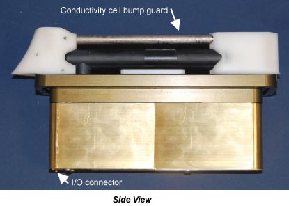
The Slocum Glider Payload CTD is a low-power profiling instrument designed specifically for installation in Slocum gliders. It has the high accuracy necessary for research, updating ocean models, assessing sensor stability on moored observatories, and leveraging data collection opportunities from operational vehicle missions. The Slocum Glider Payload CTD measures conductivity, temperature, and pressure. The T-C sensor assembly visible on the exterior of the vehicle consists of a streamlined T-C intake sail (with integral T-C duct and anti-foul device), a horizontal, externally flushed, conductivity cell, and a downstream exhaust sail attached to a rectangular science bay hatch cover. The electronics, pump motor, and pressure transducer are attached to the underside of the hatch cover and enclosed in a waterproof calibration housing.
The intake sail allows measurements to be made outside of the vehicle’s boundary flow where old water is thermally contaminated as it is dragged to a different depth by the vehicle, producing TS errors. The pump pulls water into the duct at top of the intake sail and immediately past a temperature sensor. Water then flows through an anti-foulant cylinder, through the conductivity cell into the internal pump impeller, and out the top of the exhaust sail to prevent exhaust re-circulation and Bernoulli pressure differences from changing the flow rate. The outside of the conductivity cell is free-flushed. If the cell were located inside the flooded fairing, a thermal mass error resulting from temperature difference between the poorly-flushed volume inside the hull and the ambient ocean temperature measured by the CTD would produce salinity errors.
The Slocum Glider Payload CTD evolved from sensors and measurement methods used in Argo float CTDs. Their performance and reliability has been proven on more than 8,000 Argo CTDs delivered to date. The constant pumped flow and ducted T & C sensors provide superior dynamic accuracy compared to free-flushed sensors. However, TS errors introduced by glider flight dynamics, boundary layers and wakes are larger than those experienced by vertically ascending Argo floats, reducing the achievable dynamic accuracy on gliders.
The Slocum Glider Payload CTD uses 240 mw when sampling continuously (including pump). To put this into perspective, the energy contained in just one alkaline C cell (Duracell MN1400, 9 Watt-hours or 32.4 kJoules, nominal) will operate the CTD continuously for 37 hours, or 3 days at 50% duty cycle (profiling continuously pumped at ˝ Hz on every glider upcast). In other words, the CTD will operate at 50% duty cycle for 30 days using only 4.2% of a typical Slocum glider’s alkaline energy capacity (7.8 MJ).
Two sampling modes are supported: Continuous Sampling or Spot Sampling.
Continuous Sampling (autorun = yes) runs the pump continuously at slow speed (9 ml/sec), and the CTD samples once every two seconds (˝ Hz), producing a time series suitable for application of high quality finish corrections (e.g. response filtering, alignment, thermal mass correction) for dynamic errors observed in the data.
Spot Sampling (autorun = no) acquires and transmits Pressure, Temperature, & Conductivity on command (TakeSample). For valid salinity data, the pump must be turned on for some seconds prior to sampling. The maximum salinity accuracy implied by the static calibration accuracy of the sensors will typically be achieved when approximately 110 ml are flushed before a sample is taken. There are two pumping rates. Executing the PumpFast command produces 14 ml/sec, and PumpSlow produces 9 ml/sec. PumpFast reduces thermal mass error and should usually be used for spot sampling, especially through the thermocline. Send PumpFast, wait for flushing time (user set), and then send TakeSample. The pump turns off automatically after sampling.
All data are output in ASCII characters. Users may select engineering units of decibars (pressure), degrees C (temperature), and Siemens/meter (conductivity), or raw decimal counts.
SPECIFICATIONS
|
Measurement Range |
Calibration Range |
Accuracy (within calibration range) |
Accuracy (outside calibration range) |
Resolution | |
| Conductivity |
0
to 9 S/m (0 to 90 mS/cm) |
0
to 6 S/m (0 to 60 mS/cm) |
±
0.0003 S/m (± 0.003 mS/cm) |
better than
± 0.0010 S/m
1 (± 0.010 mS/cm) 1 |
0.00001 S/m (0.0001 mS/cm) |
|
Temperature (°C) |
-5 to +42 | +1 to +32 | ± 0.002 | better than ± 0.004 1 | 0.001 |
|
Pressure (dbar) |
0 to 100, 0 to 350, 0 to 1000, 0 to 2000 |
full scale | ± 0.1% of full scale range | 0.002% of full scale range | |
| 1 Due to fit extrapolation errors. | |||||
Operating Power Requirements
Supply Voltage: 8 to 20 VDC nominal
Quiescent current: 30 µA
Continuous (1/2 Hz) Sampling: 241 mW (2.9 Watt-hours/day @ 50% duty)
Example Spot Sampling, Flushing and Sample
Timing Comparison:
(subject to change with firmware changes)
| PumpFast | PumpSlow | |
| Flow rate | 14 ml/sec | 9 ml/sec |
| Time to pump 110 ml* | 7.8 sec | 12.2 sec |
| Power to pump 110 ml | 2.56 Joules | 1.93 Joules |
| Time to end of sample after TakeSample | 2.65 sec | 2.65 sec |
| Power during sampling* | 0.74 Joules | 0.64 Joules |
| Duration of spot sample operation | 7.8 - 1.2 + 2.65 = 9.25 sec | 12.2 - 1.2 + 2.65 = 13.65 sec |
| Total power per spot sample (time) | 3.3 Joules | 2.57 Joules |
| *Includes 1.2 seconds pumping after TakeSample is sent. Recommended interval between PumpFast and TakeSample is 6.6 (7) seconds. | ||
Mechanical
Weight, CTD and integral pump: 2.0 kg (4.5 lbs) in air, 0.4 kg (0.9 lbs) in water
Calibration housing immersion depth: 10 meters maximum
REFERENCES
ADDITIONAL INFORMATION / LINKS
Links to Other Instruments of Interest
![]()
Specifications are subject to change without notice.
Sea-Bird Home Phone: (+1) 425-643-9866 E-mail: seabird@seabird.com