APPLICATION NOTE NO. 36a
Installation of P/N 50094 Conductivity Cell Tubing Connector Kit
Revised April 1998

 Print
version

To install Conductivity Cell Tubing Connector
Kit:
- Remove conductivity sensor from the CTD and remove
the cell guard from the sensor housing (4 screws).
- Remove the anode ring from the top of the sensor
housing and install the new flat-sided anode ring in its place.
- Remove the two screws at the top of the cell tray
and take the cell tray spacer out from between the cell tray and the sensor housing.
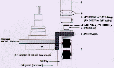
- Screw the male tubing connector (item 2) into the
connector bracket.
- Insert the connector bracket at the location of the
old cell tray spacer and measure the length of tubing (item 3, 11.1 mm [7/16"] ID x
1.6 mm [1/16"] wall)
required to connect the cell end and the connector.
- Remove the connector bracket, cut the appropriate
length of Tygon tubing (11.1 mm [ 7/16"] ID x 1.6 mm [ 1/16"]
wall) and push one end onto the tubing connector.
- Reinsert the connector bracket between the cell tray
and sensor housing, carefully pushing Tygon tubing onto the end of the conductivity cell.
Make sure the tubing is not bulged, out of line, or putting any stress on the cell end.
- Reinstall the 2 screws through the holes in the cell
tray and connector bracket.
- Replace the cell guard.
- Insert the hose barb end of the female tubing
connector (item 4) into the end of the Tygon tubing (item 5) leading from the pump intake.
Secure the tubing to the connector with nylon cable ties as shown (item 6).
- Push the male and female connectors (items 2 and 4)
together until they lock. Push the metal tab on the female connector to unlock.
Application Note Revision History
| Date |
Description |
| |
Initial release. |
![[HRule Image]](../images/div.gif)
Sea-Bird Home Phone: (+1) 425-643-9866
E-mail:
seabird@seabird.com
![]()
![]()