![]()
This application note describes the use of a Teledyne Benthos PSA-916 altimeter integrated with a Sea-Bird CTD (SBE 9plus, 19, 19plus, 19plus V2, 25, or 25plus). The altimeter can be cabled to an A/D channel on the CTD end cap; a y-cable is required if you are connecting multiple sensors to one connector.
Seasoft calculates the altimeter height as follows:
altimeter height = [300 * voltage / scale factor] + offset
where
Example Calculation in Sea-Bird Software --
For a 100 m sensor with 5 V full scale
voltage, calculate the scale factor for input in the software:
scale factor = full scale voltage * 300/full scale range = 5 * 300 / 100 = 15
If the altimeter is outputting 2.45 V, calculated height = [300 * voltage /
scale factor] + offset = 300 * 2.45 / 15 = 49 m
If no echo is received (altimeter is out of range), the altimeter actually
outputs 4.98 V (not 5 V), so the maximum calculated height in Seasoft = 300 *
4.98 / 15 = 99.6 m
Calculating and Entering Calibration Coefficients for Altimeter in Seasave V7
If Sea-Bird integrates the altimeter at the factory, we send it to you with a configuration file (.xmlcon or .con) that matches the factory setup. If you are integrating the altimeter yourself, you must update your existing configuration file to include the altimeter and to enter its calibration coefficients.
Note: You can create or modify the configuration file in Seasave V7 (real-time data acquisition software) or SBE Data Processing (post-processing software); both programs use the same configuration file.
Viewing Altimeter Data
You can view the following data related to the altimeter output in Seasave’s fixed, scrolled, and/or plot displays.
See the Seasave manual and/or Help files for details on setting up the displays.
 Setting Up Altimeter Alarms
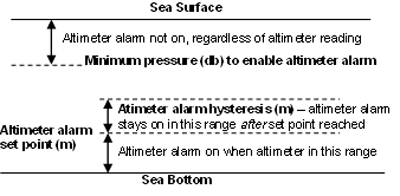
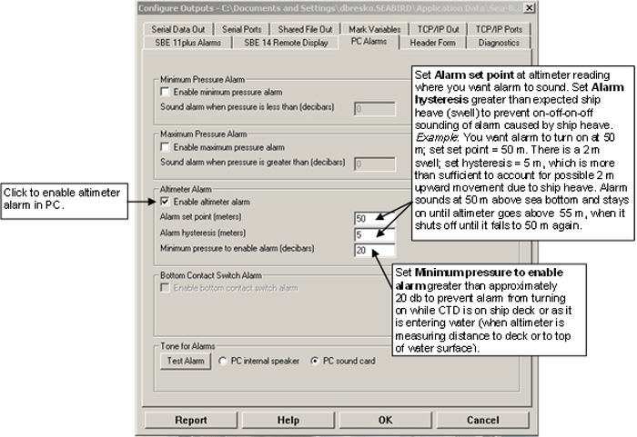
You can activate an audible alarm in the personal computer (PC) that is running Seasave, based on an altimeter, minimum and maximum pressures, and/or a bottom contact switch (pressure and bottom contact switch alarms are not covered in this application note; see the Seasave manual and/or Help files). To enable and set up the altimeter alarm:
Note: You can set up similar alarms in an SBE 11plus Deck Unit (for SBE 9plus CTD) or SBE 14 Remote Display.

After you enable one or more audible alarms on Configure Output’s PC Alarms tab, you can also enable a visual alarm in Seasave.
| In the Display menu, select Alarms. The Alarms display appears. |
 |
| If no alarm is on when Seasave is collecting data or playing back archived data, the Alarms display looks like this: |
 |
| If an alarm is on when Seasave is collecting data or playing back archived data, the display looks like this, with the two icons alternating every 0.5 seconds: |

 |
Note: See the altimeter manual for details on cleaning and testing.
Cleaning
A major source of problems with acoustic equipment is that the transducer is not clean, resulting in masking of acoustic signals. Teledyne recommends that the user clean the exterior of the pressure casing and transducer with fresh water and a mild detergent, prior to each deployment. Do not use glass cleaner.
Testing
The analog output ranges from 0 VDC to 4.98 V (which represents 0.00 to 99.6 m). If no echo is received, the output will go to full scale (4.98 V). Teledyne recommends the following tests be performed prior to deployment:
These tests can be performed with the altimeter on the CTD, by observing the altimeter channel voltage output in a Seasave display.
| Date | Description |
| January 2014 | Initial release. |
![]()
Sea-Bird Home Phone: (+1) 425-643-9866 E-mail: seabird@seabird.com