
 Print
version
This Application Note describes use of the PN 90085 Customer-Installed TC
Duct Kit, covering:
- Installation and removal of the TC (Temperature-Conductivity)
Duct Assembly on the SBE 3 temperature sensor and SBE
4 conductivity sensor on
the SBE 9 / 9plus
or SBE 25 / 25plus Sealogger CTD, when equipped with the standard sensor
mounting bracket.
- Installation of system plumbing for a CTD with pump and (optional) SBE
13 or SBE 23 Dissolved Oxygen (DO) Sensor.
Note: Sea-Bird stopped selling the SBE
13 and 23 in 2001. These were replaced by the SBE
43. The orientation / location of the SBE 43 differs from what is shown
in this application note, although the same parts are used for the plumbing.
For plumbing
installation for the SBE 43, see Application Note 64-1.
Both the installation and removal procedures require slow, deliberate
movements to avoid breaking the temperature or conductivity sensor. Therefore,
Sea-Bird recommends that you perform these procedures in a lab, not on deck.
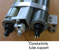 Note: Note:
If your conductivity sensor does not have a conductivity
tube support, install the conductivity tube support kit (see Application Note 36) before installing the
TC Duct and plumbing.Conductivity tube support kit:
PN 50094 for aluminum sensors
PN 50108 for titanium sensors
|
TC Duct Installation
Preparation
Parts Included in PN 90085 Kit that are Used for TC Duct Installation
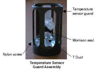
- Temperature sensor guard assembly (replaces existing temperature sensor
guard), which consists of:
Temperature sensor guard
T Duct
Morrison seal 0.026 ID x 0.24 OD, installed in T Duct
(2) Phillips-head nylon machine screws, 2-56 x 1/4, attaching T Duct to
temperature sensor guard
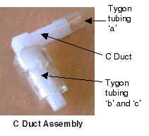
- C Duct assembly (fits into end of conductivity cell), which consists of:
C Duct
Flexible plastic (Tygon) tubing – 3 pieces:
| |
Inner Diameter (ID) |
Wall Thickness |
Approximate Length |
Function |
|
a |
6.35 mm
(0.25 in.) |
0.76 mm
(0.03 in.) |
13 mm
(0.5 in.) |
Connect C Duct to T Duct |
|
b |
6.35 mm
(0.25 in.) |
3.18 mm
(0.125 in.) |
10 mm
(0.375 in.) |
Installed under tubing 'c' to provide seal at conductivity sensor |
|
c |
11.11 mm
(0.4375in.) |
1.59 mm
(0.0625 in.) |
25 mm
(1.0 in.) |
Installed over tubing 'b' to provide seal at conductivity sensor |
|
|
|
|
|
|
Note:
See left side of drawing 67027
for part numbers.
Tools Required
Straight-edge ruler for measuring
For cutting C Duct horizontal arm (older CTDs, if necessary):
Fine-toothed (2 teeth per mm [50 teeth per in.] or finer)
backsaw
10 degree (approximate) tapering tool – a sharp pencil is
acceptable
400 grit (very fine) sandpaper
Installation
Before beginning, place the CTD cage in a horizontal position, so the
conductivity and temperature sensors are on top. For clarity, the sensors and mounting bracket are shown removed from the
CTD cage in the photos below – however, you do not need to remove the sensors
and mounting bracket from the CTD cage to install the TC Duct.
T Duct Installation
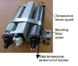
- Remove the
temperature sensor from the sensor mounting bracket:
- Unscrew the locking sleeve from the temperature sensor’s cable connector
by hand. If you must use a wrench or pliers, be careful not to loosen the
bulkhead connector instead of the locking sleeve.
- Remove the cable connector from the temperature sensor by pulling the
connector firmly away from the temperature sensor. Do not pull on the
cable.
- Loosen the mounting strap that secures the temperature and conductivity
sensors in the sensor mounting bracket.
- Slide the temperature sensor out of the mounting bracket.
- Unscrew the existing temperature sensor guard, being careful not to
damage the temperature sensor needle.
|
 |
- Install the new
temperature sensor guard assembly on the temperature sensor:
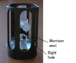
- Looking through the T Duct’s sight hole to center the temperature sensor
needle, slowly and carefully insert the temperature sensor needle into the
base of the T Duct. Do not bend or torque the needle. You will feel a
little resistance as the needle goes through the black Morrison seal in the
T Duct.
- Screw the guard on tightly (hand-tighten only).
|
 |
- Reinstall the
temperature sensor in the mounting bracket:
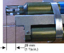
- Slide the temperature sensor into the sensor mounting bracket until the
end of the temperature sensor guard extends beyond the conductivity sensor
guard approximately 29 mm (1 1/8 in.).
- Retighten the mounting strap enough to hold the sensors in position, but
loose enough to allow the temperature sensor to slide and rotate in the
mounting bracket.
|
 |
C Duct Installation and Fit Check
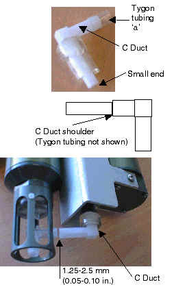
- Remove the 13 mm (0.5
in.) piece of Tygon tubing ‘a’ from the large end of the C Duct.
- Insert the small end
of the C Duct straight into the glass conductivity cell’s intake until the
Duct’s shoulder butts against the end of the cell.
- Carefully rotate the C Duct’s arm toward the temperature sensor.
- Slide and rotate the temperature sensor until the T and C Duct arms are
perfectly aligned, leaving a gap of 1.25 to 2.5 mm (0.05 to 0.10 in.) between
the ends of the Ducts.
- If the Duct arms
overlap (possible on some older systems), the C Duct must be
trimmed. Proceed to C Duct Trimming.
- Gradually tighten the sensor mounting bracket strap’s screw. Check for
changes in alignment and changes in the gap between the Duct ends. As the
sensors are secured into the bracket, the T and C Ducts usually move closer
together, reducing or eliminating the gap between the arms. Do not
continue to tighten the strap after the gap has been eliminated, as doing so
will break the conductivity cell.
- If the Duct arms are touching and either of the sensors is not secure in
the mounting bracket, the C Duct must be trimmed. Proceed to
C Duct Trimming.
When the sensors are securely tightened and there is
still a small gap of 0.5 to 1.25 mm (0.02 to 0.05 in.) between the ducts, proper
fit is verified. Proceed to Final Assembly.
|
 |
Final Assembly
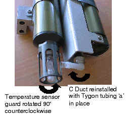
- Rotate the temperature sensor guard counter-clockwise approximately 90
degrees, so the T Duct is out of the way.
- Remove the C Duct and reinstall Tygon tubing ‘a’:
- Carefully rotate the C Duct clockwise slightly, and gently pull the C Duct
straight out from the conductivity cell.
- Reinstall Tygon tubing ‘a’ over the end of the C Duct. Leave
approximately half of the tubing hanging past the end of the C Duct.
- Reinstall the C Duct on the conductivity cell, leaving it in the rotated
position described in Step A.
|
 |
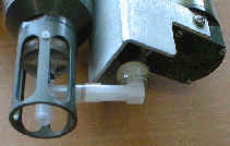
- Slowly rotate the
temperature sensor guard back into position. As you rotate, insert the end
of the T Duct into Tygon tubing ‘a’. Continue to rotate both the sensor guard and
C Duct until the T and C Ducts are
aligned. Do not apply force perpendicular to the end of the cell, as doing so will break the cell.
- Center Tygon tubing ‘a’ on the joint between the C Duct and T
Duct.
|
 |
- Reinstall the cable connector and locking sleeve on each sensor:
- Lightly lubricate the inside of the cable connector with silicone grease
(DC-4 or equivalent). Do not use WD-40 or other petroleum-based
lubricants, as they will damage the connectors.
- Install the cable connector, aligning the raised bump on the side of the
connector with the large pin (pin 1 -- ground) on the bulkhead connector.
Remove any trapped air by burping or gently squeezing the connector
near the top and moving your fingers toward the end cap.
- Place the locking sleeve over the cable connector. Tighten the locking
sleeve finger tight only. Do not overtighten the locking sleeve and do
not use a wrench or pliers.
|
|
C Duct Trimming (if necessary, as described in Steps 4 and 5 of C Duct
Installation and Fit Check) Some older systems have a different sensor mounting bracket, causing the duct
arms to overlap. For these systems, the C Duct arm must be trimmed. |
- Determine the
correct length of the C Duct arm:
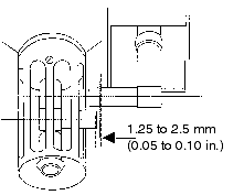
- Rotate and/or slide the temperature sensor until the center lines of the
duct arms are parallel.
- Mark the end of the C Duct for trimming, allowing for a gap of 1.25 to 2.5
mm (0.05 to 0.10 in.) between the T and C Ducts.
- Trim the C Duct arm and check for fit:
- Carefully rotate the C Duct clockwise slightly, and gently pull the C Duct
straight out from the conductivity cell.
- Trim off the end of the C Duct arm with a fine-toothed backsaw, being
careful not to crush the thin-walled Duct while cutting.
- Clean the C Duct with water to remove dust and grit.
- Reinsert the C Duct in the conductivity cell.
- Rotate and/or slide the temperature sensor until the center lines of the
horizontal duct arms are parallel, and verify that the gap between the arms
is 1.25 to 2.5 mm (0.05 to 0.10 in.). If not, mark the end of the C Duct arm
for trimming and repeat Step 2.
|
 |
- Prepare the edges
of the C Duct for final installation:
- Carefully rotate the C Duct clockwise slightly, and gently pull the C Duct
straight out from the conductivity cell.
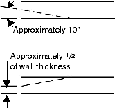
- Sand or file the cut square and flat. Remove any burrs.
- Chamfer the inside edge of the trimmed end at a 10 degree angle, leaving
approximately half the wall thickness between the end of the taper and the
outside of the duct wall. A sharpened pencil, wrapped with 400 grit
sandpaper, makes a good chamfering tool.
- Clean the C Duct with water to remove dust and grit.
- Return to C Duct Installation and Fit
Check at Step 2.
|
 |
|
C Duct and Sensor Removal
For sensor shipment and calibration, the C Duct must be disconnected from the
T Duct and removed from the conductivity cell. Note that the temperature sensor
should be shipped with the temperature sensor guard, which includes the
installed T Duct.
- Remove the conductivity and temperature sensors and mounting bracket
assembly from the CTD:
- Unscrew the locking sleeves from the temperature and conductivity sensor
cable connectors by hand. If you must use a wrench or pliers, be careful
not to loosen the bulkhead connector instead of the locking sleeve.
- Remove the cable connector from each sensor by pulling the connector
firmly away from the sensor.
- Remove the quick-release plug from the conductivity cell.
- Remove the two 9/16 inch hex head aluminum bolts that secure the mounting
bracket to the CTD’s end cap. Remove the mounting bracket from the CTD.
|
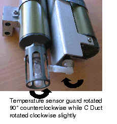
- Disconnect the T
Duct from the C Duct:
- Slowly rotate the temperature sensor guard by turning it counter-clockwise
approximately 90 degrees. At the same time, rotate the C Duct clockwise
slightly. The Tygon tube that joins the ducts flexes and slips off the T
Duct as the T Duct twists out of its position.
Note: Do not force the C Duct, as this could break the conductivity
cell. If rotating the C Duct is difficult, pour water over the duct area to
dissolve buildup around the duct.
|
 |
- Remove
the C Duct from the conductivity cell:
- Carefully rotate the C Duct clockwise more. Do not force the C Duct,
as this could break the conductivity cell. If rotating the C Duct is
difficult, pour water over the duct area to dissolve buildup around the
duct.
- Once loosened, gently pull the C Duct straight out from the conductivity
cell.
- Store the C Duct for reinstallation when the sensors have returned from
calibration.
|

 |
- Retighten
the temperature sensor guard by hand.
- Loosen the mounting bracket strap screw, and slide the sensor(s) from the
bracket. If both sensors are being shipped, SBE 9plus sensors can be shipped
in their mounting bracket.
- The conductivity cell is stored and shipped dry, to prevent damage caused
by freezing:
- Rinse the conductivity cell with clean, de-ionized water.
- Drain and gently blow-dry the conductivity cell. Do not use compressed
air, which typically contains oil vapor.
- Ship the sensor(s) in a package with cushioning material to protect them
from damage during shipment.
|
|
Plumbing Installation
Application
The remainder of this application note describes plumbing installation for a
CTD with a pump and (optional) SBE 13 or SBE 23 Dissolved Oxygen (DO) Sensor.
Sea-Bird stopped selling the SBE 13 and 23 in 2001, and began selling the SBE
43 DO Sensor. The orientation / location of the SBE 43 differs from what is
shown in this application note, although the same parts are used for the
plumbing; see Application Note 64-1 for plumbing
installation for a system including the SBE 43.
Preparation
Parts and Supplies Included in Kit
|
PN |
Description |
Quantity |
|
23337 |
Pump air release valve -- for vertical configuration
only |
1 |
|
30387 |
Tube, 1/2" Y-fitting -- for connection to pump air release valve, vertical configuration
only |
1 |
|
30388 |
Tygon tubing, 19 mm (0.75 in.) OD, 13 mm (0.5 in.)
ID |
4 ft |
|
30579 |
Tygon tubing, 13 mm (0.5 in.) OD, 9.5 mm
(0.375 in.) ID -- for connections to DO sensor |
0.5 ft |
|
30389 |
Cable tie, 102 mm (4 in.) -- to secure
tubing connections |
20 |
|
30458 |
Cable tie, 381 mm (15 in.) -- to secure
Y-fitting to main housing |
2 |
| |
|
|
Tools Required
Sharp knife or scalpel for cutting tubing
Straight-edge ruler for measuring and cutting
Installation
For plumbing installation:
- Use the minimum tubing lengths necessary, but avoid tight bends in the
tubing. Tight
bends place stress on the tubing connections at the sensors, which can lead
to failures at the connections.
- Do not place any vertical loops in the tubing. Loops trap air, preventing the pump
from working properly.
- Secure each tubing connection with two cable ties.
Plumbing installation details differ, depending on whether the sensors will
be deployed in a vertical or horizontal configuration. See
Vertical Configuration Schematic and Details and
Horizontal Configuration Schematic and Details below.
Vertical Configuration
Schematic and Details
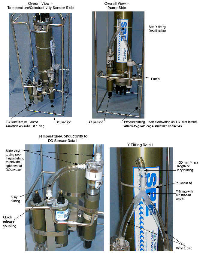
When installing plumbing for the vertical configuration:
- (for SBE 9plus only) Place the intake and exhaust on the same
horizontal plane. Attach exhaust tubing
from the pump to the cage, as shown in the schematic below. Failure to place
the exhaust tubing properly can lead to acceleration of water in the
plumbing, with resulting errors in conductivity data.
Note: Exhaust tubing is usually omitted by Sea-Bird for an SBE 25 /
25plus.
- Place the exhaust away from the intake, so the exhaust water is not pulled
into the intake. In the
photo below, the exhaust and intake are in diagonally opposing
corners. If the exhaust is too close to the intake, it will cause errors in the temperature data, because the pump transfers heat to the
exhaust water.
- Place a 25 mm (1 in.) long piece of 9.5 mm (0.375 in.) ID Tygon tubing at the DO sensor intake and exhaust. Slide
the larger diameter (13 mm ID) Tygon tubing over the smaller diameter tubing to provide tight seals.
- If the system does not include a DO sensor, connect the tubing from the
conductivity cell directly to the Y-fitting.
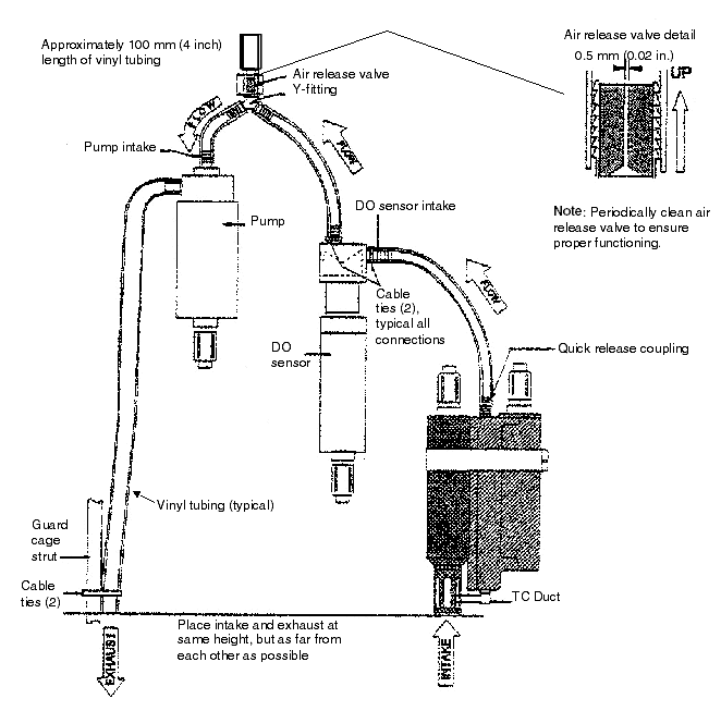
All photos are of an SBE 9plus. Secure each tubing connection with two cable
ties (not shown).
Note: Exhaust tubing is usually omitted by Sea-Bird for an SBE 25 / 25plus.
Horizontal
Configuration Schematic and Details
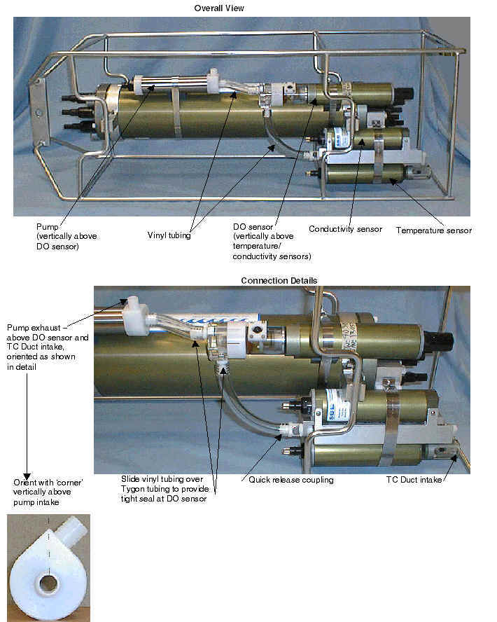
The horizontal configuration is most commonly used when the CTD is integrated with an
SBE 32 Carousel Water Sampler with an extension stand.
When installing plumbing for the horizontal configuration:
- Configure the system as follows:
- Place the DO sensor above the conductivity sensor exhaust.
- Place the pump intake above the DO sensor exhaust.
- Orient the pump with the exhaust outlet corner up.
Failure to configure the system in this manner can trap air, preventing the
pump from working properly.
- Place a 25 mm (1 in.) long piece of 9.5 mm (0.375 in.) ID Tygon tubing at the DO sensor intake and exhaust. Slide
the larger diameter (13 mm ID) Tygon tubing over the smaller diameter tubing
to provide tight seals.
If the system does not include a DO sensor, connect the tubing from the
conductivity cell directly to the pump intake.
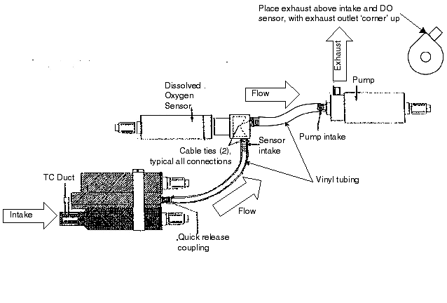
All photos are of an SBE 9plus. Secure each tubing connection with two cable
ties (not shown).
Application Note Revision History
| Date |
Description |
| 1991 |
- Initial release. |
| March 2002 |
Major revision, added pictures. |
| September 2003 |
- Note that exhaust tubing for
vertical configuration not used by Sea-Bird with SBE 25.
- Add PN for kit -- 90085 and updated kit (adding more small cable
ties for attaching tubing and larger cable ties for attaching
y-fitting to housing).
- Refer to application note 64-1 for plumbing if using SBE 43.
- Add detail on reconnecting cables after installing TC Duct,
lubricate with silicone, donít use WD-40. |
| October 2012 |
- Update for SBE 25plus. |
![]()
 Note:
Note:


![]()