![]()
|
|
 |
The Glider Payload CTD (GPCTD) measures conductivity, temperature, and pressure, and optionally, dissolved oxygen (with the modular SBE 43F DO sensor). It is a modular, low-power profiling instrument for autonomous gliders with the high accuracy necessary for research, inter-comparison with moored observatory sensors, updating circulation models, and leveraging data collection opportunities from operational vehicle missions. The pressure-proof module allows glider users to exchange CTDs (and DO sensors) in the field without opening the glider pressure hull.
The GPCTD evolved from sensors and measurement circuits used in Argo float CTDs. Their performance and reliability has been proven on more than 8,000 Argo floats to date. The constant pumped flow and ducted T & C sensors provide superior dynamic accuracy compared to free-flushed sensors. However, TS errors introduced by glider flight dynamics, boundary layers, and wakes are larger than those experienced by vertically ascending Argo floats, reducing the achievable dynamic accuracy on gliders.
Recent improvements in efficiency have yielded a continuously pumped CTD that consumes only 175 mW while recording at 1 Hz, or 190 mW when transmitting real-time data. To put this in perspective, the energy contained in one Alkaline D cell will operate the CTD continuously for 114 hours, or 9.5 days, at 50% duty cycle (profiling continuously at 1 Hz on every glider upcast). One Lithium DD cell will provide 48 days profiling continuously on every upcast.
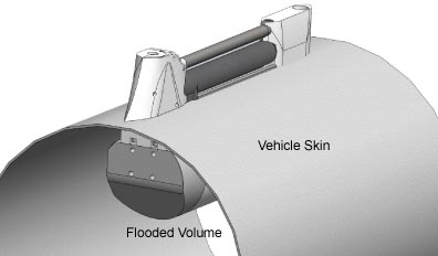
The T-C sensor assembly visible on the exterior of the vehicle consists of a streamlined T-C intake sail (with integral T-C duct and anti-foul device), a horizontal, internal field conductivity cell, and a downstream exhaust sail with pump connections. The intake sail allows measurements to be made outside of the vehicle’s boundary flow where old water is thermally contaminated by the vehicle, producing TS errors. The pump pulls water into the duct at top of the intake sail and immediately past a temperature sensor. Water then flows through an anti-foulant cylinder, through the conductivity cell, and out the top of the exhaust sail to prevent exhaust re-circulation and Bernoulli pressure differences from changing the flow rate. The outside of the conductivity cell is free-flushed to minimize salinity errors. If the cell were located inside the flooded fairing, a thermal mass error resulting from temperature difference between the poorly-flushed volume inside the hull and the ambient ocean temperature measured by the CTD would produce salinity errors.
The connecting neck, electronics housing, modular pump, and DO sensor are meant to locate in a flooded space inside the glider hull. Pump tubing between the conductivity cell and the pump intake, and from the pump outlet to the exhaust fitting on the sail, are not shown. The locations of the pump and DO sensor within the flooded volume are not pre-determined, but tubing lengths should be short as possible and avoid sharp bends, and the pump (centrifugal impeller) and tubing orientation should avoid trapping air that will interfere with pump priming.
Four sampling modes are supported:
Data from Continuous or Interval Sampling are stored in memory for later upload. If desired, data can also be output in real-time (increasing power consumption slightly). A Send Last Sample command can be executed without interrupting Continuous or Interval Sampling; if the GPCTD is taking a sample in Interval Sampling mode when the command is sent, the reply is delayed slightly until the current sample is completed.
A file header (20 bytes) is created each time Continuous or Interval Sampling is initiated, and contains beginning and ending sample numbers, sample mode, time between samples, and cast starting date/time. A maximum of 1000 headers (casts) can be stored.
|
Note: Oxygen connector optional if SBE 43F not ordered; oxygen connector included if SBE 43F ordered. |
|
SPECIFICATIONS
|
Measurement Range |
Calibration Range |
Accuracy (within calibration range) |
Accuracy (outside calibration range) |
Resolution | |
| Conductivity |
0
to 9 S/m (0 to 90 mS/cm) |
0
to 6 S/m (0 to 60 mS/cm) |
±
0.0003 S/m (± 0.003 mS/cm) |
better than
± 0.0010 S/m
1 (± 0.010 mS/cm) 1 |
0.00001 S/m (0.0001 mS/cm) |
|
Temperature (°C) |
-5 to +42 | +1 to +32 | ± 0.002 | better than ± 0.004 1 | 0.001 |
|
Pressure (depth) (dbar) |
0 to 100, 0 to 350, 0 to 1000, 0 to 2000 |
full scale | 0.1% of full scale range | -- | 0.002% of full scale range |
|
1 Due to fit extrapolation errors. |
|||||
Memory
8 Mbytes = 699,000 samples of CTP (194 hours at 1 Hz), or 559,000 samples of CTP & DO (155 hours at 1 Hz)
Data Formats
Real-time data and uploaded data are output (decimal or Hexadecimal characters) in units of Siemens/meter (conductivity), degrees C (temperature), decibars (pressure), and Dissolved Oxygen frequency.
Operating Power Requirements
Supply Voltage: 8 to 20 VDC nominal (power calculations below assume 10.0 V)
Quiescent current: 30 µA
Continuous (1 Hz) Sampling
Fast Interval Sampling
Slow Interval Sampling
Spot Sampling:
Battery Power Notes:
Mechanical
Weight, CTD and pump:
Weight, SBE 43F DO sensor:
ADDITIONAL INFORMATION / LINKS:
Documentation -- manual, photos, technical papers, application notes, etc.
Sales Information -- options, accessories, cables, mount kits, spares, etc.
Software -- components of Seasoft V2
Links to Other Instruments of Interest
![]()
Specifications are subject to change without notice.
Sea-Bird Home Phone: (+1) 425-643-9866 Fax: (+1) 425-643-9954 E-mail: seabird@seabird.com