APPLICATION NOTE NO. 64-1
Plumbing Installation -- SBE 43 DO Sensor and Pump on a CTD
Revised April 2008
![]()
This Application Note describes installation of an SBE 43 Dissolved Oxygen (DO) Sensor and pump (and associated plumbing) for:
Preparation
Parts Included in PN 90087 Universal Plumbing Kit
| PN | Description | Quantity |
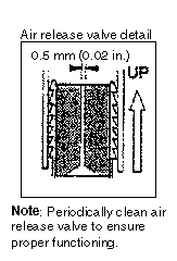
| 23337 | Pump air release valve -- for vertical configuration only | 1 |
| 30387 | Tube, 1/2" Y-fitting -- for connection to pump air release valve, vertical configuration only | 1 |
| 30388 | Tygon tubing, 19 mm (0.75 in.) OD, 13 mm (0.5 in.) ID | 4 ft |
| 30579 | Tygon tubing, 13 mm (0.5 in.) OD, 9.5 mm (0.375 in.) ID -- for connections to DO sensor | 0.5 ft |
| 30389 | Cable tie, 102 mm (4 in.) -- to secure tubing connections | 20 |
| 30458 | Cable tie, 381 mm (15 in.) -- to secure Y-fitting to main housing | 2 |
Tools Required
Sharp knife or scalpel for cutting tubing
Straight-edge ruler for measuring and cutting
Installation
Note for SBE 9plus or 25:
If your conductivity sensor does not have a conductivity tube support, install the conductivity tube support kit before installing the plumbing (see Application Note 36 for installation details).Conductivity tube support kit:
Part Number 50094 for aluminum sensors
Part Number 50108 for titanium sensors
Basic considerations for plumbing installation:
Plumbing installation details differ, depending on whether the sensors will be deployed in a horizontal or vertical configuration. See Horizontal Configuration Schematic and Details and Vertical Configuration Schematic and Details below.
Horizontal Configuration Schematic and Details
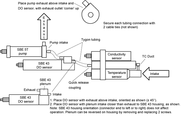
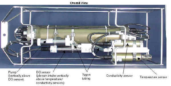
The horizontal configuration is most commonly used when the CTD is integrated with an SBE 32 Carousel Water Sampler with an extension stand. When installing plumbing for the horizontal configuration:
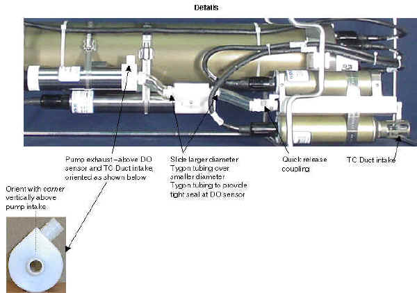
- Place the DO sensor intake above the conductivity sensor exhaust.
- Place the pump intake above the DO sensor exhaust.
- Orient the pump with the exhaust outlet corner up.
Failure to configure the system in this manner can trap air, preventing the pump from working properly.
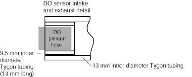
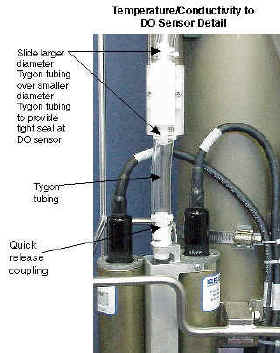
DO sensor intake and exhaust tubing detail:
Secure each tubing connection with two cable ties (not shown).
Vertical Configuration Schematic and Details
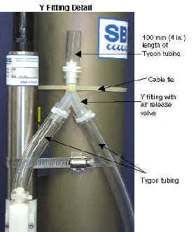
When installing plumbing for the vertical configuration:
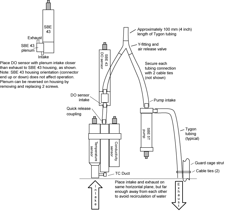
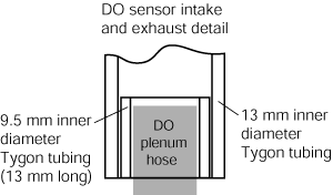
DO sensor intake and exhaust tubing detail:
 |
 |
Secure each tubing connection with two cable ties.
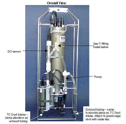
Note: Exhaust tubing is usually omitted by Sea-Bird for an SBE 19, 19plus, 19plus V2, or 25.
 |
 |
Preparation
Parts Included in PN 90087 Universal Plumbing Kit
| PN | Description | Quantity |
| 30388 | Tygon tubing, 19 mm (0.75 in.) OD, 13 mm (0.5 in.) ID | 4 ft |
| 30579 | Tygon tubing, 13 mm (0.5 in.) OD, 9.5 mm (0.375 in.) ID -- for connections to DO sensor | 0.5 ft |
| 30389 | Cable tie, 102 mm (4 in.) -- to secure tubing connections | 20 |
| 23337 | Pump air release valve -- not used for moored applications | 1 |
| 30387 | Tube, 1/2" Y-fitting -- not used for moored applications | 1 |
| 30458 | Cable tie, 381 mm (15 in.) -- not used for moored applications | 2 |
Tools Required
Sharp knife or scalpel for cutting tubing
Straight-edge ruler for measuring and cutting
Installation
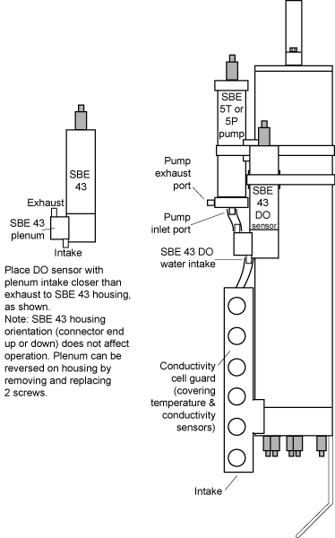
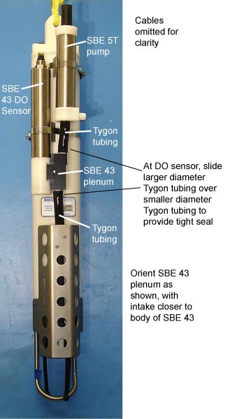
Basic considerations for plumbing installation:
- Place the DO sensor intake above the conductivity sensor exhaust.
- Orient the DO sensor plenum with the intake closer than the exhaust to the sensor body.
- Place the pump intake above the DO sensor exhaust.
Failure to configure the system in this manner can trap air, preventing the pump from working properly.
 |
 |
Application Note 64: SBE 43 Dissolved Oxygen Sensor -- Background Information, Deployment Recommendations, and Cleaning and Storage
Application Note 64-2: SBE 43 Dissolved Oxygen Sensor Calibration and Data Corrections using Winkler Titrations
Application Note 64-3: SBE 43 Dissolved Oxygen Sensor -- Hysteresis Corrections
![]()
Last modified: 05 May 2010
Sea-Bird Home Phone: (+1) 425-643-9866 Fax: (+1) 425-643-9954 E-mail: seabird@seabird.com